Hi, I recently started designing and printing parts for WPL C14/24 and I’m trying to advertise my models. I would like to offer this Free STL download to the community to help people out and also get my name out there more (Liang's RC). It would be greatly appreciated if I could get a shoutout to my instagram page (https://www.instagram.com/
Details about the STL:
WPL's V3 PCB is a great upgrade for their little trucks. However, many people including myself struggle to fit the V3 electronics into the C14/24 because the space under the hood is fairly small to begin with and the stock tray was designed for mass production RTR components. To address this, I’ve designed a sleek and durable electronics tray that lets you early fit the stock servo, V3 board and speaker under the hood. It’s a clean install that requires no modification of factory parts and retains all factory mounting points for the body and bumper.
Print settings:
Slicer: Cura standard quality profile
Material: PLA
Nozzle temp: 195
Bed temp (glass bed with glue stick): 40
Layer height: 0.2mm
The servo holder should be printed upside-down
Pictures:
See attached.
Assembly Notes
The electronics tray comes as a kit with the main tray holding together a number of component trays.
Large rectangular 'locating pins' are used to ensure the component trays go in the proper place. While the pins are designed to press fit together, hobby glue is recommended for the strongest assembly. Slight trimming or sanding of the locating pins may be necessary depending on your printers accuracy.
Holes that are designed to hold screws may need to be enlarged depending on the quality of your print. A 1/16 drill bit may be used to expand the holes to the proper size. Attempting to thread a screw into a hole that is too small runs the risk of snapping the surrounding plastic.
Using extra screws that came with your C14/24 kit is recommended. If you do not have extra screws then M2 screws or equivalent should work as well. The assembly instructions below make reference to standard WPL screws.
Assembly Instructions
Step 1 - Print all your parts :)
Step 2 - Place the main tray on a flat surface. Take a locating pin and press it into the main tray until the bottom of both components are flush.
Step 3 - Snap the speaker tray onto the portion of the locating pin protruding from the main tray.
Step 4 - Drop the speaker into the speaker tray, lining up the wire with the relief cut-out in the tray.
Step 5 - Slide the servo into the servo holder ensuring the WPL sticker is facing up (into the tray). If you have a servo horn, turn it to the side and place the bottom of the servo onto a flat surface with the servo holder on top.
Step 6 - Press the other locating pin into the top of the servo holder until it bottoms out on the servo.
Step 7 - Press the PCB tray onto the portion of the locating pin protruding from the servo holder.
Step 8 - Drop the PCB into the PCB holder, securing it with a single #3 screw (see picture)
Step 9 - Drop the completed servo holder assembly into the main tray, aligning the front of the servo holder with the main tray’s opening.
Step 10 - Through the bottom of the main tray, use 4 #1 screws to secure the servo tray to the main tray.
Step 11 - Mount the headlights onto the main tray using 2 #3 screws.
Step 12 - Mount the on/off switch to the main tray using 2 #2 screws.
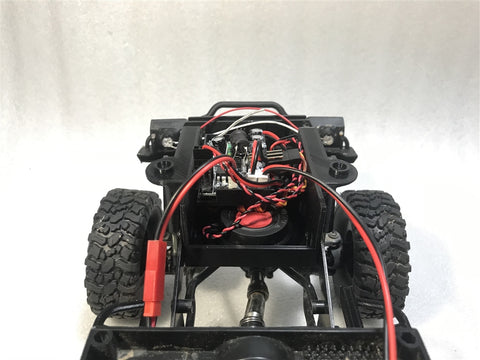
Step 13 - Install main tray between frame rails of your C14/24
Step 14 - Plug in all your electronics. Space is provided on the right side of the main tray for extra wiring; bunch them up or zip tie them for an ultra clean install.
Step 15 - Test everything to make sure things work well. Be careful of battery polarity!!
Step 16 - Done!
I have a similar kit that allows a Hobby Wing 1625, 1060 or 1080 into the C14/24 as well. I’ve attached a couple pics of it as well as some of my other prints too just so you can see what they look like.
STL Files Download, Click here